Understanding and Controlling Cap Sink Marks

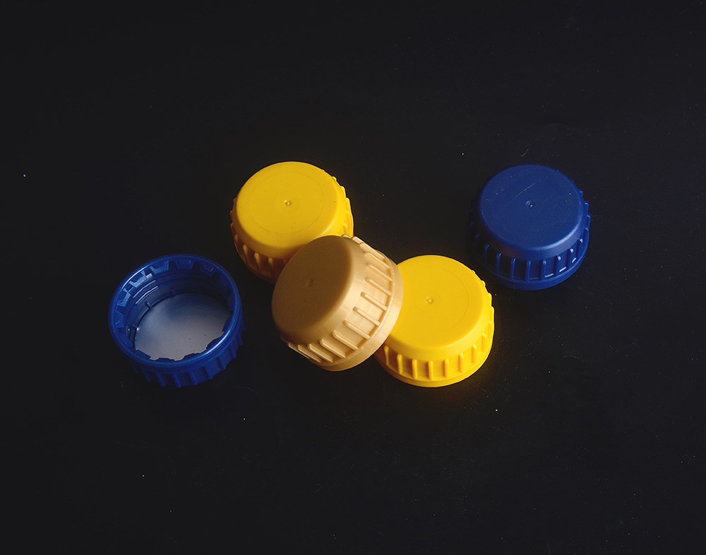
Sink marks are surface depressions that occur in the thicker sections of injection-molded caps. These cosmetic defects are not just an aesthetic issue—on bottle caps, they can compromise sealing surfaces and create leak paths . This article explores the causes of sink marks and provides practical solutions for controlling them.
What Causes Sink Marks?
Sink marks form when thicker sections of the cap cool and shrink more slowly than surrounding areas. During cooling, the outer material solidifies first, creating a rigid skin. As the inner material continues to cool and contract, it pulls the surface inward, leaving a depression .
For bottle caps, sink marks most commonly occur in three areas: above ribs or bosses , at the gate area where material is thickest , and on sealing surfaces, where even minor depressions create leak paths .
Sink marks are more pronounced in semi-crystalline materials like polypropylene and HDPE, where molecular rearrangement during cooling creates greater volumetric shrinkage . The visibility of a sink mark depends more on its width than its depth—wide, shallow depressions are often more visible than narrow ones .
Solutions: A Three-Pronged Approach
Effective sink mark control requires addressing three areas simultaneously: part design, mold design, and processing conditions.
Part Design Modifications
The most effective solution is preventing thick sections from forming in the first place. Design caps with uniform wall thickness wherever possible . When ribs or bosses are necessary, keep them at 50-70% of the adjacent wall thickness (0.5T to 0.7T) to minimize shrinkage effects . Avoid merging bosses directly with side walls, which creates thick sections that are prone to sinking .
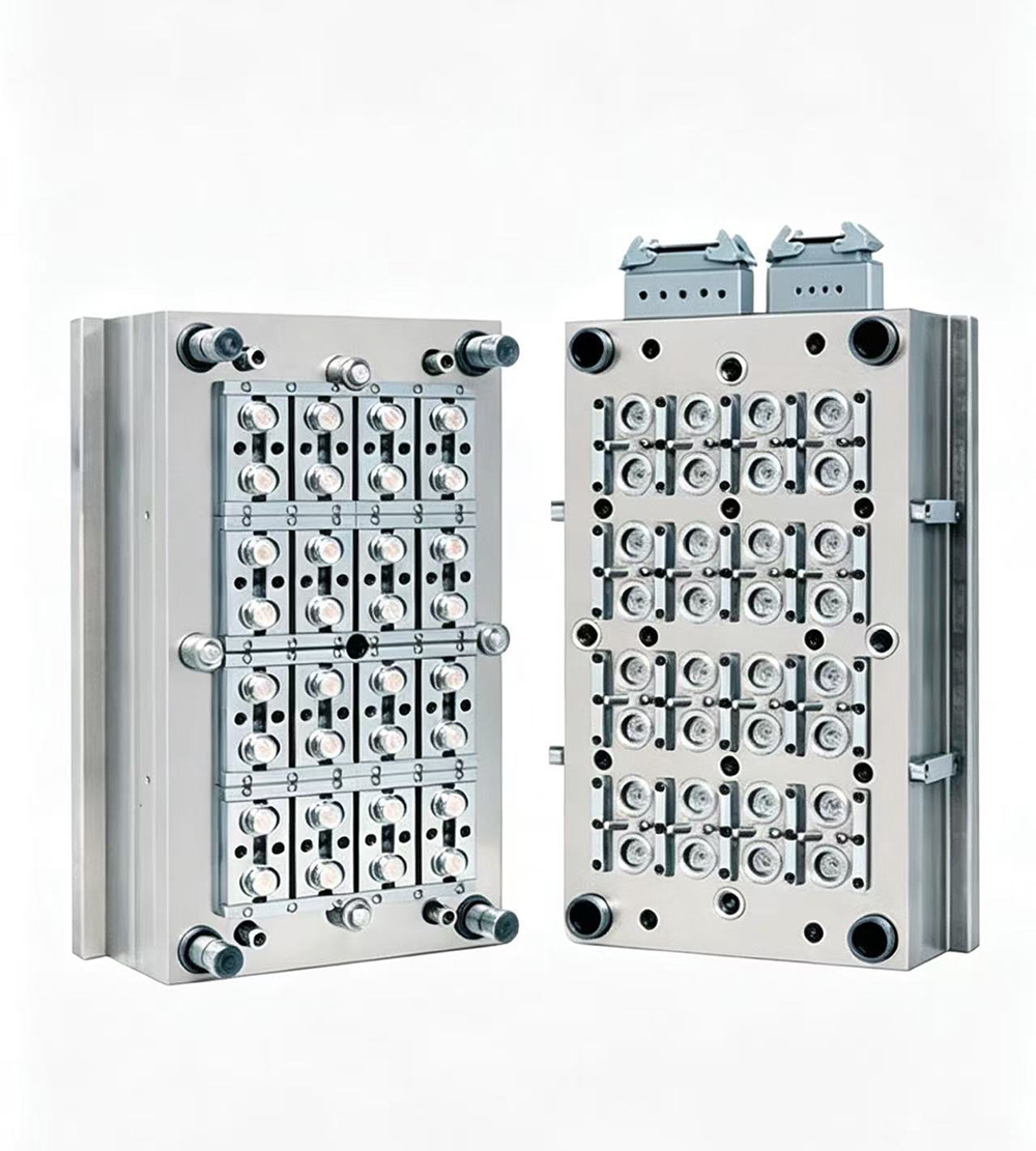
Mold Design Solutions
Strategic gate placement is essential. Locating gates over thick sections allows packing pressure to compensate for shrinkage during the critical cooling phase . Enlarging gates and runners delays gate freeze-off, extending the time available for effective packing .
A case study on a molded protector part found that increasing the sprue bush hole diameter eliminated sink marks by extending gate sealing time, reducing cycle time from 83 seconds to 67 seconds—a savings of over $1,000 per month in operating costs .
Processing Adjustments
Processing parameters are the most adjustable variable. Increasing packing pressure and extending holding time improves compensation for volumetric shrinkage . Higher packing pressure forces more material into the cavity during cooling, filling voids before they form.
Reducing mold temperature accelerates solidification, creating a stiffer outer skin that resists inward pull . A cooler mold also increases the elastic modulus of the skin by 20-30% . Optimizing cooling time ensures the part is fully solidified before ejection .
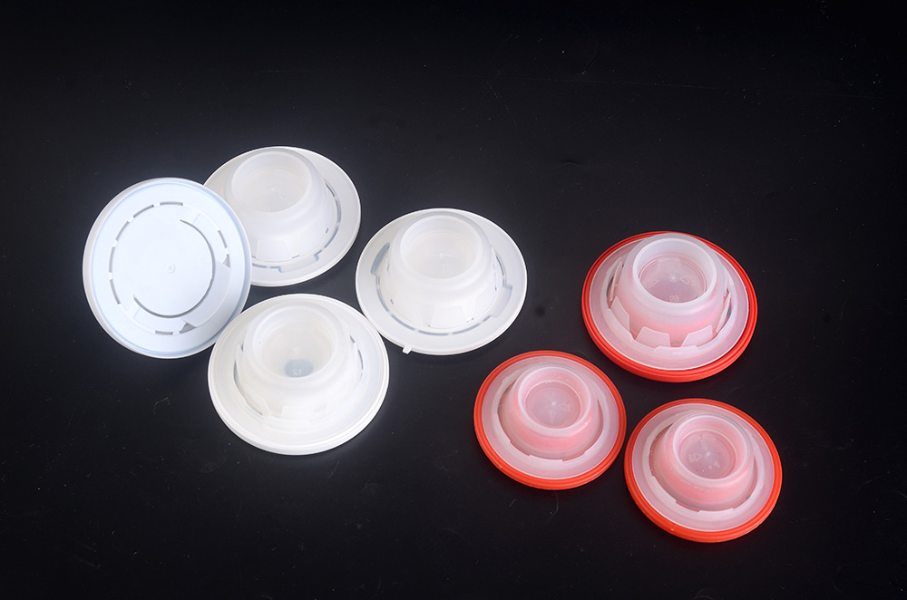
Sink Marks on Cap Sealing Surfaces
When sink marks appear on sealing surfaces, they create leak paths that compromise product integrity . Solutions include optimizing packing pressure, increasing cooling time, reducing wall thickness variation, and adjusting gate location .
Conclusion
Sink marks in bottle caps are a manageable defect when approached systematically. By balancing part design, mold design, and processing optimization, manufacturers can produce caps with smooth, consistent surfaces that meet both aesthetic and functional requirements. The key lies in understanding the physics of shrinkage and applying the right countermeasures at the right stage of production.